How to Test a Used Motherboard and CPU: Step-by-Step UK Guide
Advertisement
In the UK second-hand PC hardware market, bundling a used motherboard and CPU is one of the smartest ways to shave hundreds of pounds off a custom build. Sourcing an AMD Ryzen 5 5600X and a solid B550 board as a combo can cost as little as £120 to £140 on the used market, compared to over £220 brand new. However, motherboards are highly complex, multi-layered circuit boards with hundreds of micro-traces, capacitors, and delicate socket pins. A single bent LGA pin or a microscopic scratch near a mounting hole can turn your bargain into an expensive paperweight.
Unlike graphics cards, which can be dropped into an existing system and stress-tested in ten minutes, a motherboard and CPU form the absolute foundation of your PC. Fault-finding them after they are fully mounted inside a case is a nightmare of disassembly. This guide walks you through a systematic, data-dense, out-of-case testing plan to qualify your used motherboard and CPU before you mount them.
For broader component safety tips, make sure to read our guide on is it safe to buy used PC parts in the UK? and consult our comprehensive how to test used PC parts checklist. If you are still in the market looking for parts, our used motherboard buying guide highlights what to look for when negotiating a deal.
Phase 1: Pre-Power Physical Audit
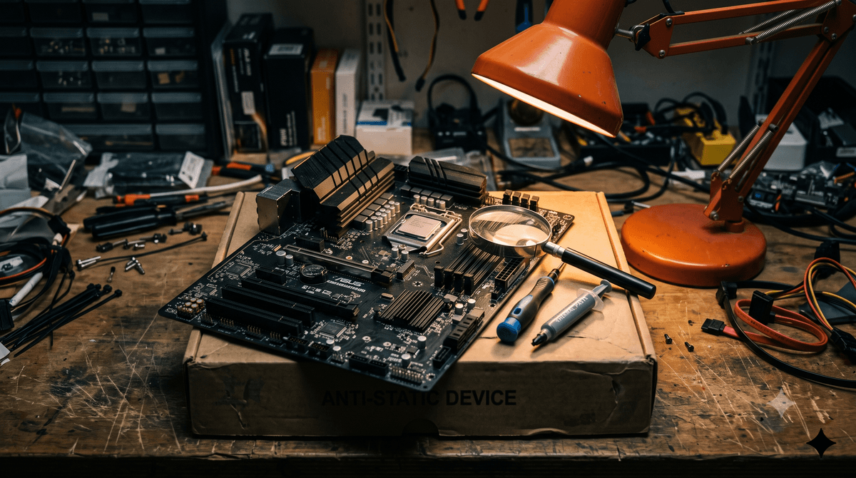
Never apply power to a second-hand motherboard or CPU without a meticulous visual inspection. Shorting out a board due to a bent pin or a stray piece of solder can permanently damage the processor or the power supply. Use a high-quality smartphone camera zoom or a magnifying glass under strong overhead light to conduct these checks.
1. The CPU Socket Check (The LGA vs. PGA Inspection)
How you inspect the socket depends entirely on whether you are running an Intel platform (LGA) or an older AMD platform (PGA vs. AM5 LGA).
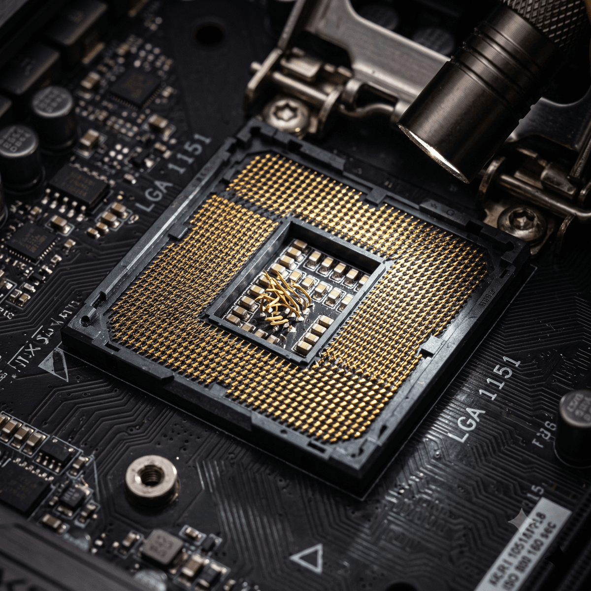
The pins are on the motherboard socket itself. They are extremely fragile. Shine a flashlight across the socket from different angles. The gold pins should form a perfectly uniform, reflective grid. If you notice a dark spot, a glint of light bouncing in the wrong direction, or a pin that looks misaligned, it is bent. Do not install a CPU in a socket with bent pins; this can bridge contacts and kill the chip.
The pins are on the bottom of the CPU package. Place the CPU on a flat surface and look down the rows of pins from all four edges. They should align like rows of corn. A classic trick is to gently slide a thin plastic credit card between the rows. If the card snags or bumps, you have a bent pin. Also check for missing pins—an AM4 CPU can sometimes boot with missing grounding pins, but missing memory channel pins will render it partially dead.
2. Motherboard PCB Scratches and SMD Damage
Flip the motherboard over and inspect the back, particularly around the CPU socket backplate and the mounting holes. UK system builders often use incorrect screws or slip with a screwdriver, severing the microscopic copper traces layered within the PCB. If you see bright copper showing through the dark solder mask (usually black or green), the trace is broken.
Next, look at the front of the board. Inspect the surface-mounted device (SMD) capacitors near the PCIe slots and the edges of the RAM slots. Heavy graphics cards installed without support can sag and shear off these tiny grey or black resistors. If you find empty solder pads with jagged metal edges, a component has been knocked off.
Phase 2: The Out-of-Case POST Test
Breadboarding is the practice of assembling the core PC components outside of the chassis on a non-conductive surface. If you install everything directly into a case and it fails to boot, you will waste hours trying to determine if the culprit is a faulty motherboard, a dead CPU, a short circuit against the metal case standoffs, or a loose power cable.
Step-by-Step Out-of-Case Assembly
Install the CPU and Cooler
Carefully align the triangle marker on the CPU corner with the triangle on the socket. Lower the retention arm. Apply a pea-sized dot of thermal paste, and mount a basic CPU cooler. Always plug the cooler fan wire into the primary CPU_FAN header. Many motherboards feature built-in safety logic that shuts down power within 3 seconds if no RPM signal is detected on this header to prevent thermal damage.
Seat a Single RAM Stick
Insert only one stick of DDR4 or DDR5 RAM. Consult the motherboard markings or manual to find the primary slot (typically labeled DIMM_A2 or slot 2 from the CPU). Using a single stick reduces the variables during the initial POST test.
Connect the PSU Cables
Plug in the 24-pin ATX main power connector and the 8-pin (or 4+4 pin) EPS CPU power connector. Ensure both clips click firmly into place. If you are using a dedicated graphics card (required if your CPU lacks integrated graphics), install it in the top PCIe x16 slot and connect the appropriate PCIe power cables.
Plug in the Video and Keyboard
Connect your monitor cable (HDMI or DisplayPort) to the motherboard rear I/O if your CPU has an integrated GPU (e.g., Intel non-F processors or AMD G-series/Ryzen 7000+). If using a discrete GPU, connect the cable directly to the graphics card. Connect a basic USB keyboard.
Jump-Start the Board
Locate the front panel header block (usually bottom-right of the board). Find the two pins labeled PW_SW, PWR_BTN, or Power Switch. Take a clean, flat-head screwdriver and touch it across these two metal pins for half a second. This completes the circuit, acting exactly like pushing the power button on a case.
Reading the Debug LEDs
Most modern motherboards have a set of four small diagnostic lights called **EZ Debug LEDs** near the 24-pin power connector (labeled CPU, DRAM, VGA, and BOOT). When you jump-start the board, watch these lights. They should cycle through one by one. If the boot process halts and a light stays lit, it points directly to the failing system node:
The board cannot communicate with the processor. Common causes: missing 8-pin CPU power cable, outdated motherboard BIOS that does not support the CPU generation, or bent pin(s) in the socket.
Memory detection failed. The RAM stick is either faulty, seated in the wrong slot, or the CPU memory controller is failing due to socket pressure or pin damage.
Graphics initialization failed. The system cannot find an iGPU or discrete graphics card, or the GPU is missing PCI-Express power connectors.
The hardware POST is successful. The motherboard is functional and searching for a bootable device (like a Windows SSD). This is a PASS for basic functionality.
Phase 3: BIOS Level Auditing
If your EZ Debug LEDs pass and your monitor lights up, tap the Deleteor F2 key repeatedly to enter the Motherboard BIOS. The BIOS is your first source of hardware telemetry. Do not skip this step; a motherboard can boot to BIOS but exhibit major voltage instability or thermal issues.
System Specification and Memory Channel Audit
In the main menu or system status screen, check the detected components:
- CPU Model and Clocks: Confirm the CPU model matches the listing exactly. Check the base clock speed.
- BIOS Version: Note the date. If you are testing a newer CPU on an older board (like a Ryzen 5000 on a B450, or Intel 14th Gen on a Z690), ensure the BIOS is updated to a version that officially supports that CPU model.
- RAM Capacity and Slots: Verify that the BIOS reports the exact size of your installed RAM module. After this initial pass, turn off the system, install your second stick of RAM in the secondary channel (usually slot 4), and confirm that the system registers both sticks running in **Dual-Channel Mode**.
Voltage Rail Diagnostics
Navigate to the hardware monitor tab (often named **PC Health Status**, **Hardware Monitor**, or **System Monitor**). Find the DC voltage readouts. The motherboard VRM (Voltage Regulator Module) and PSU must supply power within strict ATX tolerances. If voltages fall outside these ranges, the board or PSU is faulty:
| Voltage Rail | Target Voltage | Acceptable Range (ATX Spec) | Primary Function |
|---|---|---|---|
| +12V | 12.00 V | 11.40 V – 12.60 V | Powers CPU VRMs, PCIe slots, and high-draw fans. |
| +5V | 5.00 V | 4.75 V – 5.25 V | Powers USB ports, logic circuits, and SATA controllers. |
| +3.3V | 3.30 V | 3.135 V – 3.465 V | Powers motherboard chipsets, PCI slots, and M.2 NVMe controllers. |
Idle Thermal Baseline
Let the system sit idle in the BIOS hardware monitor for five minutes. Because modern BIOS interfaces run the CPU without any power saving or C-states active, this mimics a light active load.
- CPU Temperature: Should stabilize between 32°C and 48°C (depending on whether you are using a stock cooler or a large dual-tower heatsink). If it climbs past 65°C and continues to rise, turn off the system immediately. Your cooler is either not making contact, the plastic protective film was left on the heatsink cold plate, or the pump in your liquid cooler is dead.
- Motherboard / VRM Temperature: Should read between 30°C and 42°C. Elevated idle VRM temps point to a failing MOSFET or a missing/degraded thermal pad under the VRM heatsink blocks.
Phase 4: OS-Level Stability and Stress Testing
Booting to BIOS proves that the motherboard and CPU can handle basic I/O and display tasks. It does not prove that they are stable under a heavy rendering load, when memory channels are saturated, or when data is flying through all PCIe lanes. To verify this, boot into a test installation of Windows. (You can use a spare SSD or a bootable USB drive running Windows To Go).
1. Dual-Channel Memory and DIMM Slot Check
A common point of failure for used motherboards is a **dead memory channel**. This is usually caused by physical trace damage on the motherboard PCB, or bent pins in the LGA socket that correspond to the memory controller lines on the CPU.
How to verify memory channels:
- Install a RAM stick in slot 2 (
DIMM_A2). Boot the system. - Shut down, move the stick to slot 4 (
DIMM_B2). Boot the system. - Install sticks in both slots 2 and 4. Open Windows Task Manager, click **Performance**, then **Memory**. Verify that it lists the correct capacity (e.g., 32 GB) and shows the speed matching your hardware (e.g., 3200 MHz or 6000 MHz).
- If the system boots with RAM in slot 2 but loops or sounds three long beeps (RAM error) when a stick is placed in slot 4, the motherboard or the CPU memory controller has a fault. You have a dead channel, and the board should be returned.
2. CPU Heavy Load Testing (Cinebench R23)
Download **Cinebench R23** (free). Run the **Multi-Core Test** on a 10-minute continuous loop. Cinebench taxes the CPU execution engines and cache without pulling unrealistic current like synthetic power viruses.
- Watch the run in HWiNFO64. The CPU should boost to its rated clocks and settle into its TDP limit (e.g., 65W for non-X chips, 105W+ for high-performance units).
- Check your Cinebench score against online reviews for the same processor. If your score is 15% or more below average, the CPU is thermal throttling or the motherboard VRM is unable to supply clean current, forcing the CPU clock multipliers down.
3. Synthetic Motherboard VRM Burn-In (Prime95 Small FFTs)
To test the power delivery stages of the motherboard, run **Prime95** and select the **Small FFTs** option. This test loads the FPU (Floating Point Unit) and pulls maximum power, generating intense heat.
4. PCIe Lane Integrity Check
A scratched trace on the board can cause a PCIe x16 slot to drop down to x8 or x4 speeds, or fall back to an older PCIe generation (e.g., running at Gen 2.0 instead of Gen 4.0). This severely bottlenecks modern graphics cards.
Open **GPU-Z** with your graphics card installed. Look at the **Bus Interface** field. It should read something likePCIe x16 4.0 @ x16 4.0. If it reads something likePCIe x16 4.0 @ x4 1.1, click the small question mark symbol next to the field. This launches a small 3D render test to load the GPU. If the link does not immediately ramp up to @ x16 4.0 (or whatever generation the card and slot support), you have damaged PCIe lanes on either the CPU or the motherboard slot.
5. Input/Output and Port Sweep
Finally, run a systematic sweep of the physical ports on the motherboard rear I/O. A motherboard with a blown USB controller chip might boot perfectly but fail to read devices when plugged into specific ports.
Take a USB flash drive and plug it into every USB port on the back. Ensure Windows detects and mounts the drive each time.
Plug in an RJ45 cable and verify internet connectivity. Connect headphones to the 3.5mm jack; listen for static or channel imbalance.
If the board features multiple M.2 slots, test an NVMe SSD in each slot to confirm they are registered in the BIOS.
UK Buying Context & Legal Considerations
Buying second-hand computer parts in the UK requires an understanding of your legal protections. The level of cover you receive depends entirely on whether you purchased the parts from a business seller, a private individual on a platform, or via local pickup.
1. Business vs. Private Sales (The Consumer Rights Act 2015)
If you buy a used motherboard or CPU from a registered business seller in the UK (such as a refurbished PC shop or professional merchant), you are protected by the **Consumer Rights Act 2015**. Under this law, the goods must be:
- Of satisfactory quality: The item must match its description, taking into account its age and used status.
- Fit for purpose: It must perform the tasks you would reasonably expect (i.e., a motherboard must boot and run stably).
If you discover a fault within the first 30 days of receiving the item from a business seller, you have a legal right to reject it and demand a full refund.
However, if you buy from a **private seller** (e.g., a forum member or standard individual listing), the rules change. The principle of caveat emptor (buyer beware) applies. The seller is not legally obliged to disclose faults; they are only required to ensure that the item matches the description. If the listing states "working motherboard" and it arrives with a dead memory channel, the item is **not as described**, which is your primary legal basis for a refund dispute.
2. Shipping Risks: Royal Mail and Couriers
Motherboards are highly sensitive to shipping damage. When buying a shipped item, always check how the seller intends to package it. It must be wrapped in a static-shielding bag. Bubble wrap wrapped directly around bare motherboard solder points can generate electrostatic charges that destroy component logic before you ever power it on.
If an item arrives damaged due to poor courier handling (such as a crushed box resulting in a cracked PCB), the seller is responsible for making a claim with the shipping courier (Royal Mail, Evri, or DPD). Do not throw away the packaging. Take photos of the box, the static bag, and the damage on the board immediately.
Frequently Asked Questions
Can I fix bent socket pins on a motherboard?
If you only have one or two slightly misaligned pins, you can attempt to fix them. Use a mechanical pencil with the lead retracted. Slide the hollow metal tip of the pencil over the bent pin and gently bend it back into alignment. Use a magnifying glass. If the pin is severely crimped or broken off, the motherboard requires professional repair or socket replacement, which in the UK costs around £40–£60—often more than the value of a mid-range motherboard.
Why does my motherboard show a DRAM light, but the RAM works in another PC?
This indicates that the memory signal is failing between the CPU and the memory slots. The issue could be dust inside the DIMM slots, bent motherboard socket pins (which break the connection between the CPU memory controller and the board), or a degraded memory controller on the CPU. Remove the CPU and inspect the socket pins.
Is it safe to buy a CPU that has been "delidded"?
Delidding involves removing the metal heat spreader (IHS) of the CPU to apply liquid metal directly to the silicon die for lower temps. If done properly, it offers excellent thermals. However, it voids the manufacturer warranty, exposes the die to physical cracking under cooler pressure, and carries a high risk of chemical short-circuits from running liquid metal. Unless you are an experienced enthusiast, avoid delidded CPUs.
What does it mean if my motherboard has a missing capacitor?
If a small surface-mount capacitor has been sheared off near the PCIe slot or CPU socket, the board might still boot. However, it has lost filtering capability on that electrical trace. Under heavy load, the voltage ripple will increase, leading to random BSODs, GPU crashes, or file corruption. It is highly recommended to reject or return boards with missing SMD components.
Shop Verified Second-Hand Motherboards and CPUs on Koukan
Avoid the risks of unchecked private sales. Koukan is the UK's dedicated PC hardware marketplace, offering buyer protections and escrow transactions that give you the time to inspect and run your testing suite before the sale is finalized.
Advertisement